|
|||
|
|
|||||||||||||||||||||||||||||||||||||||||||||||||||||||||||||||||||||||||||||||||||||||||||||||||||
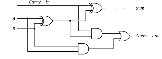


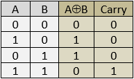
The full adder adds the values of two bits A and B, if
both bits are equal to 1 then it passed through the value of the carry to the next calculation level.
For the first loop (rightmost bit) the input carry equals to 0. In order to add two bytes, we can add 8 full adders (see next example).
|
|
|||
|
|||
|
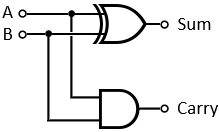
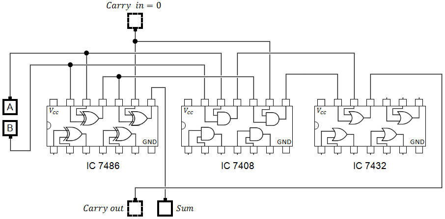
The basic circuit for adding two bits contains the chips IC 7486 - quad XOR gate, IC 7408 - quad AND gate and IC 7432 quad OR gate.
We used only half of the gates of the XOR and AND gates and only 1 of the OR gate. All the chips have to be connected to the input voltage at Vcc and to the ground at GND input.
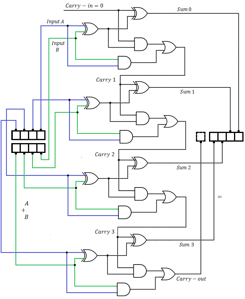
The carry out values can be connected to the carry input of the next pair of bits and so on until we reach the number of bits that should be added, see next example for 4 bits addition, this case uses all the inputs of the three types of chips 7486, 7408 and 7432. |
|
|||||
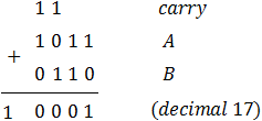
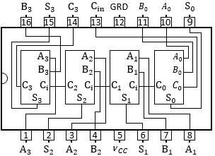
The 4 bits adder adds the values of two 4 bits values
and gives the result at right, notice that the result contains additional carry that can be used for the next higher calculations.
This process can be easily extended to more bits.
|
|
|||
|
|
||||||||||||||||||||||||||||||||||||||||||||||||||||||||||||||||||||||||||||||||||||||||||||||||||||
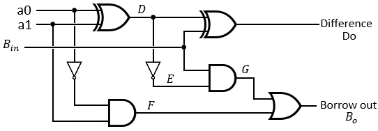
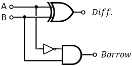
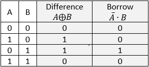
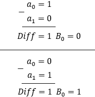
The full subtractor can find the difference between 2 bits a0 and a1, if
a0 = 0 and a1 = 1 it passes a borrow to the next calculation level.
For the first loop (rightmost bit) the input borrow equals to 0. so Bin = 0.
|
|
|||
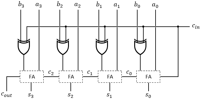
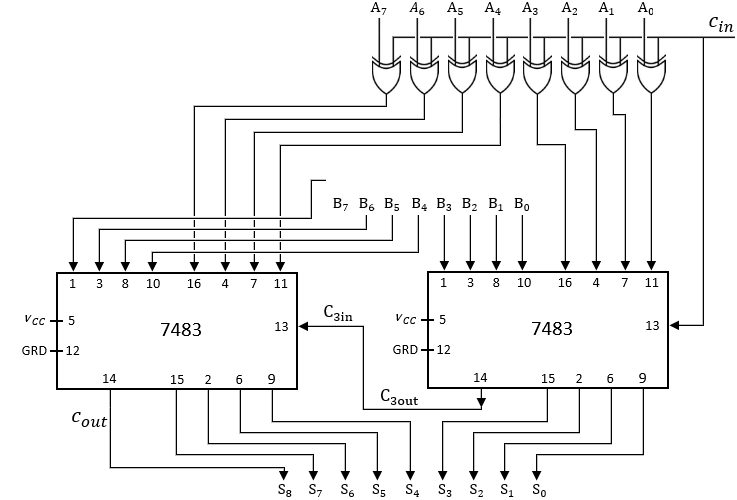
A Binary Adder-Subtractor is a type of circuit that is used to perform both operations, Addition and Subtraction. circuit’s type of operation depends on the value of the input carry Cin. If the value of Cin is 0 than addition is performed, other way if the value of Cin equal 1 then subtraction is performed. in this case we receive the result as the 2's complement. |
|
|||||||||||||||||||||||||||||||||||||||||||||||||||||||||||||||||||||||||
The carry in Cin is connected to the XOR gates along with of all the inputs of B numbers, this carry is operated as addition when Cin = 0 and as subtraction when Cin = 1. 0
0
0
0
0
0
0
0
0
0
0
0
0
0
0
0
0
0
0
0
0
0
0
0
0
+
Calculation details:
|
|||||||||||||||||||||||||||||||||||||||||||||||||||||||||||||||||||||||||


